
Build an ESP32 Obstacle-Avoiding Robot: Step-by-Step Tutorial
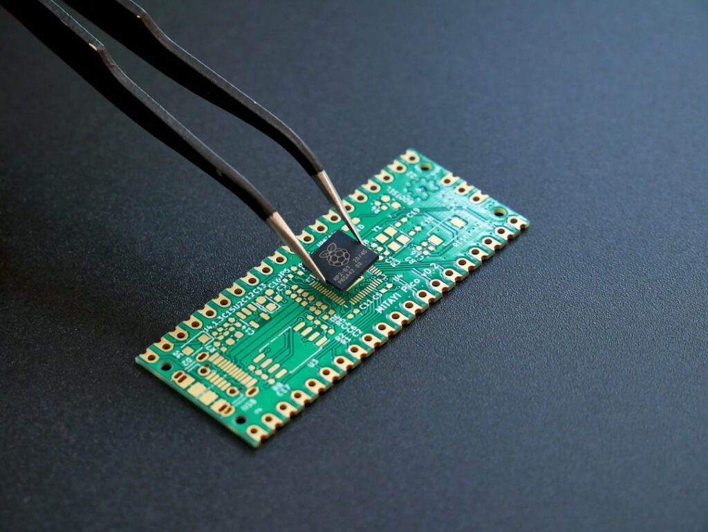
This beginner-friendly project combines an ESP32 development board, two geared motors and an ultrasonic distance sensor to create a small robot that moves forward and changes direction when it detects an obstacle. The same platform can later be expanded with Bluetooth, Wi-Fi control or additional sensors.
What you will build
The ESP32 reads the distance in front of the robot. When the path is clear, both motors move forward. When an object is too close, the robot stops, reverses briefly and turns before continuing.
Components required
- ESP32 development board
- Two DC geared motors and wheels
- Dual-channel motor driver suitable for the motors
- Ultrasonic distance sensor
- Robot chassis and caster wheel
- Battery pack, switch and suitable regulator
- Jumper wires, mounting hardware and a breadboard or PCB
Important electrical check
Confirm the motor voltage, stall current and motor-driver rating before wiring. Motors should not be powered directly from ESP32 pins. Connect the controller and motor-driver grounds together, and protect the ESP32 from voltages above its permitted input level. If the ultrasonic module returns a 5 V echo signal, use an appropriate divider or level shifter.
Step 1: Assemble the chassis
Mount the motors firmly and check that both wheels rotate without rubbing. Place the battery low and near the centre so the robot remains stable while turning. Mount the distance sensor at the front with a clear field of view.
Step 2: Wire the motor driver
Connect each motor to one driver channel. Connect the direction inputs to four ESP32 GPIO pins and the enable inputs to PWM-capable pins if speed control is required. Add a power switch between the battery and the system.
Step 3: Connect the distance sensor
Connect trigger to an ESP32 output pin and echo through the correct level-conditioning circuit to an input pin. Keep sensor wires away from motor leads where possible because motor noise can create unstable readings.
Step 4: Use a simple control loop
read distance
if distance is greater than safe_distance:
    move forward
else:
    stop
    reverse briefly
    turn right
Begin with a safe distance of approximately 20 to 30 cm, then adjust it for the robot’s speed and braking distance. Take several sensor readings and reject impossible values to reduce false turns.
Step 5: Test safely
- Lift the wheels and test motor direction.
- Confirm distance readings through the serial monitor.
- Place the robot on the floor at low speed.
- Test with a large flat obstacle.
- Adjust timing, speed and distance thresholds.
Troubleshooting
The ESP32 resets when motors start
The battery or regulator may be unable to supply peak current, or motor noise may be reaching the controller. Use suitable power regulation, decoupling capacitors and shorter power wiring.
The robot turns the wrong way
Reverse the affected motor connections or correct that channel’s direction logic in software.
Distance readings jump randomly
Check the ground connection, sensor mounting, echo voltage and nearby reflective surfaces. Median filtering across several readings can improve stability.
Next improvements
Add wheel encoders for straighter movement, a servo-mounted sensor for scanning, Bluetooth control for manual driving or a web dashboard for live status. Make one improvement at a time and test it against the original working version.